I just received a small toy car chassis that I ordered a couple of weeks ago. Therefore, I decided to start the Moving Robot project, which I am just doing for fun. Today, I was just able to assemble the chassis and build a simple circuit to make the robot move. I used an Arduino Nano to and an L293D Dual H-Bridge to control the motors. I will later be adding a variety of sensors to it. Below is a video of it working (I just ran a basic Arduino code to test if everything is working fine).
I modified the project from the arduino starter kit (Touch Sensor Lamp). Now it lights up an LED when your hand is close on the aluminium foil (without even touching it). This can be used as a 'Touch-less Switch'. How is it useful? Well, I just did it because it seemed pretty cool to me! The circuit schematic and the code can be found below:
The LED would light up only with a secret push button combination. In this case, Press button 1 two times and then press button 2 one time to light up the LED.
CIRCUIT:
The Circuit for this project is pretty simple, with just 1 LED and 2 push buttons attached to assigned pins in the code (see code below). As you can see I have four buttons on the circuit in the above picture; the two buttons on the right are just to make it more secure. They have nothing to do with the circuit (fake buttons).
You can use this as a keypad by including more push buttons. And, when a certain combination is pressed a task is performed (i.e. lights up an LED, open a lock etc.)
(Of course, you can change the code and set your own password. Contact me if you need any help and I'll be posting the circuit schematic soon. Meanwhile, you can use the above picture for reference)
CODE:
//PUSH BUTTON KEYPAD //Programmed by, Umar Rao /* CIRCUIT ---- consists of one LED and two push buttons, with 220 ohm resistors. The code clearly tells what pins to connect the LED and the push buttons. WHAT IT DOES ---- The LED would light up only with a secret push button combination. Press button 1 two times and then press button 2 one time. This combination would light the LED. */ const int buttonPin = 4; // connect push button 1 to pin 4 (with a 220 ohm resistor) const int buttonPin2 = 5; // connect push button 2 to pin 5 (with a 220 ohm resistor) const int ledPin = 6; // connect the led to pin 6 (with a 220 ohm resistor) // Variables will change: int buttonPushCounter = 0;// counter for the number of button presses int buttonPustCounter2 = 0; int buttonState = 0; // current state of the button int lastButtonState = 0; // previous state of the button void setup() { // initialize the button pin as a input: pinMode(buttonPin, INPUT); // initialize the LED as an output: pinMode(ledPin, OUTPUT); // initialize serial communication: Serial.begin(9600); } void loop() { // read the pushbutton input pin: buttonState = digitalRead(buttonPin); // compare the buttonState to its previous state if (buttonState != lastButtonState){ // if the state has changed, increment the counter if (buttonState == HIGH) { // if the current state is HIGH then the button // wend from off to on: buttonPushCounter += 1; Serial.println("on"); Serial.print("number of button pushes: "); Serial.println(buttonPushCounter); } } lastButtonState = buttonState; if (buttonPushCounter == 2) { buttonState = digitalRead(buttonPin2); if (buttonState != lastButtonState) { if (buttonState == HIGH) { digitalWrite(ledPin, HIGH); } else { digitalWrite(ledPin, LOW); } } } }
By using just an arduino, a bluetooth module and an android device, one can pretty much control what ever he wants (LEDs, motors, etc.) using voice commands. I am still working on the project! The original project shows how you can control a couple of LEDs. I successfully managed to do that and decided to take this idea to the next level.
Circuit is pretty simple, so I won't be posting a picture of the schematic. Still if you are having any trouble see the pictures of the original circuit below:
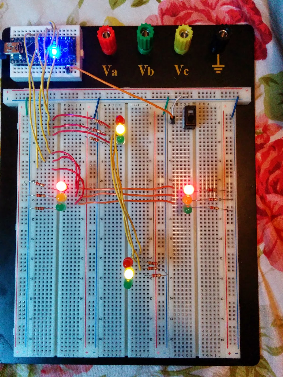
(1) The North - South LEDs are the same, so they will be connected together and then the output would go to the assign pins (See the code, to know which pins I used to the LEDs).
- The Red led to Pin 2
- The Yellow led to Pin 3
- The Green led to Pin 4
(2) Same goes for the East - West LEDs.
- The Red led to Pin 6
- The Yellow led to Pin 7
- The Green led to Pin 8
(3) Make sure to use resistor with every single LED to prevent it from any high current damage.
(4) I included the switch to turn ON and OFF the traffic lights (This step is optional).
CODE:
// 4 Way Traffic Light Controller
// Programmed by, Umar Rao
// For Circuit Schematic go to http://arduinocoder.blogspot.com
Components Required:
(1) LED BAR (You can also use LEDs instead)
(2) 10 resistors (220 - 330 ohm)
(3) ONE 3.3M ohm resistor (Or, use multiple resister to make them equivalent to 3.3M ohm)
(4) Wires!
(5) Probe (basically, a wire)
SCHEMATIC:
Here, I just used an Android Nano instead of Arduino Uno. And, also used three- 1M resistors and one- 220 ohm resistor instead of usingone- 3.3M resistor. (You can use what ever you want!)
CODE: (by Collin Cunningham)
// EMF Detector for LED Bargraph v1.0 // 5.12.2009 // original code/project by Aaron ALAI - aaronalai1@gmail.com // modified for use w/ LED bargraph by Collin Cunningham // collin@makezine.com #define NUMREADINGS 15 void setup(); void loop(); int senseLimit = 15; int probePin = 5; int val = 0; int LED1 = 11; int LED2 = 10; int LED3 = 9; int LED4 = 8; int LED5 = 7; int LED6 = 6; int LED7 = 5; int LED8 = 4; int LED9 = 3; int LED10 = 2; int readings[NUMREADINGS]; int index = 0; int total = 0; int average = 0; void setup() { pinMode(2, OUTPUT); pinMode(3, OUTPUT); pinMode(8, OUTPUT); pinMode(9, OUTPUT); pinMode(10, OUTPUT); pinMode(11, OUTPUT); Serial.begin(9600); for (int i = 0; i < NUMREADINGS; i++) readings[i] = 0; } void loop() { val = analogRead(probePin); if(val >= 1){ val = constrain(val, 1, senseLimit); val = map(val, 1, senseLimit, 1, 1023); total -= readings[index]; readings[index] = val; total += readings[index]; index = (index + 1); if (index >= NUMREADINGS) index = 0; average = total / NUMREADINGS; if (average > 50){ digitalWrite(LED1, HIGH); } else{ digitalWrite(LED1, LOW); } if (average > 150){ digitalWrite(LED2, HIGH); } else{ digitalWrite(LED2, LOW); } if (average > 250){ digitalWrite(LED3, HIGH); } else{ digitalWrite(LED3, LOW); } if (average > 350){ digitalWrite(LED4, HIGH); } else{ digitalWrite(LED4, LOW); } if (average > 450){ digitalWrite(LED5, HIGH); } else{ digitalWrite(LED5, LOW); } if (average > 550){ digitalWrite(LED6, HIGH); } else{ digitalWrite(LED6, LOW); } if (average > 650){ digitalWrite(LED7, HIGH); } else{ digitalWrite(LED7, LOW); } if (average > 750){ digitalWrite(LED8, HIGH); } else{ digitalWrite(LED8, LOW); } if (average > 850){ digitalWrite(LED9, HIGH); } else{ digitalWrite(LED9, LOW); } if (average > 950){ digitalWrite(LED10, HIGH); } else{ digitalWrite(LED10, LOW); } Serial.println(val); } } int main(void) { init(); setup(); for (;;) loop(); return 0; }